Iranian Classification Society Rules

< Previous | Contents | Next >
PART B
RECOMMENDATIONS FOR CERTAIN TYPES OF SHIPS AND ADDITIONAL GUIDELINES
CHAPTER 1 GENERAL
1.1 Purpose
The purpose of this part of the Guidance is to:
.1 recommend stability criteria and other measures for ensuring the safe operation of certain types of ships to minimize the risk to such ships, to the personnel on board and to the environment.
1.2 Application
1.2.1 This part of the Guidance contains recommended intact stability criteria for certain ships and other marine vehicles not included in Pt A or intended to supplement those in particular cases regarding size or operation.
1.2.2 Administrations may impose additional requirements regarding the design aspects of novel design or ships not otherwise covered by the Guidance.
types of of Pt A
ships of
1.2.3 The criteria
applied.
stated in this part should give as a guidance if no national requirements are
86 Guidance Relating to the Rules for the Classification of Steel Ships 2015
Pt 1 Classification and Surveys
Annex 1-2 Guidance for Intact Stability Pt 1, Annex 1-2
![]()
CHAPTER 2 RECOMMENDED DESIGN CRITERIA FOR CERTAIN TYPES OF SHIPS
2.1 Fishing vessels
2.1.1 Scope
The provisions given hereunder apply to decked seagoing fishing vessels as defined in 2(Definitions) of the INTRODUCTION. The stability criteria given in 2.1.2 and 2.1.3 below should be complied with for all conditions of loading as specified in 3.4.1.6, unless the Administration is satisfied that operating experience justifies departures therefrom.
2.1.2 Recommended general criteria*
* Refer to regulation III/2 of the 1993 Torremolinos Protocol.
2.1.2.1 The general intact stability criteria given in Pt A, 2.2.1 to 2.2.3 should apply to fishing
![]()
vessels having a length of 24 ![]() and over, with the exception of requirements on the initial metacentric height
and over, with the exception of requirements on the initial metacentric height ![]() (Pt A, 2.2.4), which, for fishing vessels, should not be less than 0.35
(Pt A, 2.2.4), which, for fishing vessels, should not be less than 0.35 ![]() for single-deck vessels. In vessels with complete superstructure or vessels of 70
for single-deck vessels. In vessels with complete superstructure or vessels of 70 ![]() in length and over the metacentric height may be reduced to the satisfaction of the Administration but in no case should be less than 0.15 .
in length and over the metacentric height may be reduced to the satisfaction of the Administration but in no case should be less than 0.15 .
2.1.2.2 The adoption by individual countries of simplified criteria which apply such basic stabil- ity values to their own types and classes of vessels is recognized as a practical and val-
uable method of economically judging the stability.
2.1.2.3 Where arrangements other than bilge keels are provided to limit the angle of roll, the
Administration should be satisfied that the stability criteria referred to in 2.1.2.1 are main- tained in all operating conditions.
2.1.3 Severe wind and rolling criterion(weather criterion) for fishing vessels
2.1.3.1 The Administration may apply the provisions of Pt A, 2.3 to fishing vessels of 45 ![]() length and over.
length and over.
![]()
2.1.3.2 For fishing vessels in the length range between 24 ![]() and 45 , the Administration may
and 45 , the Administration may
![]()
apply the provisions of Pt A, 2.3. Alternatively the values of wind pressure(see Pt A, 2.3.2) may be taken from the following table:
( | ) | 1 | 2 | 3 | 4 | 5 | 6 and over |
( | ) | 316 | 386 | 429 | 460 | 485 | 504 |
![]()
where ![]() is the vertical distance from the centre of the projected vertical area of the vessel above the waterline, to the waterline.
is the vertical distance from the centre of the projected vertical area of the vessel above the waterline, to the waterline.
2.1.4 Recommendation for an interim simplified stability criterion for decked fishing vessels under 30 ![]() in length
in length
2.1.4.1 For decked vessels with the minimum metacentric.
![]()
a length less than 30 , the following approximate formula for
![]()
where:
![]()
![]()
is the length of the vessel on the waterline in maximum load condition ( )
![]()
![]() is the actual length of enclosed superstructure extending from side to side of the vessel ( )
is the actual length of enclosed superstructure extending from side to side of the vessel ( )
![]()
![]() is the extreme breadth of the vessel on the waterline in maximum load condition ( )
is the extreme breadth of the vessel on the waterline in maximum load condition ( )
![]()
![]()
is the depth of the vessel measured vertically amidships from the base line to the top of the upper deck at side ( )
![]()
![]() is the smallest freeboard measured vertically from the top of the upper deck at side to the actual waterline ( ).
is the smallest freeboard measured vertically from the top of the upper deck at side to the actual waterline ( ).
Guidance Relating to the Rules for the Classification of Steel Ships 2015 87
Pt 1 Classification and Surveys
Annex 1-2 Guidance for Intact Stability Pt 1, Annex 1-2
![]()
The formula is applicable for vessels having:
.1 ![]() between 0.02 and 0.2;
between 0.02 and 0.2;
.2 ![]() smaller than 0.6;
smaller than 0.6;
![]()
.3 between 1.75 and 2.15;
.4 sheer fore and aft at least equal to or exceeding the standard sheer prescribed in regulation 38(8) of the International Convention on Load Lines, 1966 or the Protocol of 1988 as amended, as applicable; and
![]()
.5 height of superstructure included in the calculation is not less than 1.8 .
For ships with parameters outside the above limits the formula should be applied with special care.
![]()
2.1.4.2 The above formula is not intended as a replacement for the basic criteria given in 2.1.2 and 2.1.3 but is to be used only if circumstances are such that cross curves of stability, curve and subsequent![]() curves are not and cannot be made available for judging a
curves are not and cannot be made available for judging a
particular vessel's stability.
![]()
2.1.4.3 The calculated value of , should be compared with actual ![]() values of the vessel
values of the vessel
in all loading conditions. If an inclining experiment based on estimated displacement, or an- other approximate method of determining the actual ![]() is used, a safety margin should be
is used, a safety margin should be
![]()
added to the calculated min .
2.2 Pontoons
2.2.1 Application
The provisions given hereunder apply to seagoing pontoons. A pontoon is considered to be nor- mally:
.1 non self-propelled;
.2 unmanned;
.3 carrying only deck cargo;
.4 having a block coefficient of 0.9 or greater;
.5 having a breadth/depth ratio of greater than 3; and
.6 having no hatchways in the deck except small manholes closed with gasketed covers.
2.2.2 Stability drawings and calculations
The following information is typical of that required to be submitted to the Administration for approval:
.1 lines drawing;
.2 hydrostatic curves;
.3 cross curves of stability;
.4 report of draught and density readings and calculation of lightship tudinal centre of gravity;
.5 statement of justification of assumed vertical centre of gravity; and
.6 simplified stability guidance such as a loading diagram, so that the in compliance with the stability criteria.
2.2.3 Concerning the performance of calculations The following guidance is suggested:
.1 no account should be taken of the buoyancy of deck cargo except
equately secured timber;
displacement and longi-
pontoon may be loaded
buoyancy credit for ad-
.2 consideration should be given to such factors as water absorption(e.g., timber), trapped water
in cargo(e.g., pipes) and ice accretion;
.3 in performing wind heel calculations:
3.1 the wind pressure should be constant and for general operations be considered to act
on a solid mass extending over the length of the cargo deck and to an assumed height above the deck;
3.2 the centre of gravity of the cargo should be assumed at a point mid-height of the car- go; and
3.3 the wind lever should be taken from the centre of the deck cargo to a point at one half the mean draught;
88 Guidance Relating to the Rules for the Classification of Steel Ships 2015
Pt 1 Classification and Surveys
Annex 1-2 Guidance for Intact Stability Pt 1, Annex 1-2
![]()
.4 calculations should be performed
.5 the down-flooding angle should
covering the full range of operating draughts; and
be taken as the angle at which an opening through which
progressive flooding may take place is immersed. This would not be an opening closed by a watertight manhole cover or a vent fitted with an automatic closure.
2.2.4 Intact stability criteria
2.2.4.1 The area under the righting lever curve up to the angle of maximum righting lever
![]()
should not be less than 0.08 .
![]()
![]()
2.2.4.2 The static angle of heel due to a uniformly distributed wind load of 540 (wind speed 30 ) should of wind heeling moment is measured from the centroid of the
windage area
to half the draught.
for for
for
![]()
![]()
≤ : 20 ;
≥ : 15 ;
intermediate length: by interpolation.
2.3 Containerships greater than 100 ![]() in length
in length
2.3.1 Application*
* Since the criteria in this section were empirically developed with the data of containerships less than 200 ![]() in length, they should be applied to ships beyond such limits with special care.
in length, they should be applied to ships beyond such limits with special care.
These requirements apply to containerships greater than 100 ![]() in length as defined in
in length as defined in
2(Definitions) of the INTRODUCTION. They may also be applied to other cargo ships in this length range with considerable flare or large water plane areas. The Administration may apply
the following criteria instead of those in Pt A, 2.2.
2.3.2 Intact stability
![]()
2.3.2.1 The area under the righting lever curve(![]() curve) should not be less than
curve) should not be less than
![]()
up to ![]() = 30
= 30![]() angle of heel, and not less than
angle of heel, and not less than ![]() up to
up to
![]()
= 40 or the angle of flooding (as defined in Pt A, 2.2) if this angle is less than 40 .
2.3.2.2 Additionally, the area under the righting lever curve(![]() curve) between the angles of
curve) between the angles of
![]()
![]()
![]()
heel of 30 and 40 or between 30° and , if this angle is less than 40 , should not be less than .
2.3.2.3 The righting lever should be at least ![]() at an angle of heel equal or great-
at an angle of heel equal or great-
![]()
er than 30 .
![]()
![]()
2.3.2.4 The maximum righting lever should be at least .
2.3.2.5 The total area under the righting lever curve(![]() curve) up to the angle of flooding
curve) up to the angle of flooding
![]()
![]()
where:
![]()
![]()
= mean draught ( )
![]()
′ = moulded depth of the ship, corrected for defined parts of volumes within the hatch coamings according to the following formula:
![]()
′ , as defined in
Guidance Relating to the Rules for the Classification of Steel Ships 2015 89
Pt 1 Classification and Surveys
![]()
Annex 1-2 Guidance for Intact Stability Pt 1, Annex 1-2
where,
![]()
![]()
= moulded depth of the ship ( );
![]()
![]()
= moulded breadth of the ship ( );
![]()
= length of each hatch coaming within
![]()
( )(see Fig 2.3-1);
![]()
= mean width of hatch coamings within
![]()
( )(see Fig 2.3-1);
![]()
= mean height of hatch coamings within
forward and aft from amidships forward and aft from amidships forward and aft from amidships
![]()
= height of the centre of mass above base, corrected for free surface effect, not be
![]()
taken as less than ( );
![]()
= block coefficient;
![]()
= water plane coefficient;
![]()
![]()
![]()
= breadth of the ship on the waterline ( );
![]()
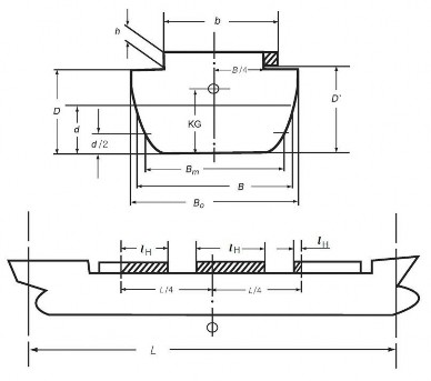
Fig 2.3-1
The shaded areas in Fig 2.3-1 represent partial volumes within the hatch coamings consid- ered contributing to resistance against capsizing at large heeling angles when the ship is on a wave crest.
2.3.2.7 The use of electronic loading and stability instrument is encouraged in determining the
ship's trim and stability during different operational conditions.
90 Guidance Relating to the Rules for the Classification of Steel Ships 2015
Pt 1 Classification and Surveys
Annex 1-2 Guidance for Intact Stability Pt 1, Annex 1-2
![]()
2.4 Offshore supply vessels
2.4.1 Application
2.4.1.1 The provisions given hereunder apply to offshore supply vessels, as defined in 2(Definitions) of the INTRODUCTION, of 24 ![]() in length and over. The alternative stability
in length and over. The alternative stability
criteria contained in 2.4.2 apply to vessels of not more than 100 ![]() in length.
in length.
2.4.2 Stability criteria
2.4.2.1 The stability criteria given in Pt A, 2.2 should apply to all offshore supply vessels ex- cept those having characteristics which render compliance with Pt A, 2.2 impracticable.
2.4.2.2 The following equivalent criteria should be applied where a vessel's characteristics render compliance with Pt A, 2.2 impracticable:
.1 the area under the curve of righting levers(![]() curve) should not be less than 0.07
curve) should not be less than 0.07
![]()
![]()
up to an angle of 15![]() when the maximum righting lever( ) occurs at
when the maximum righting lever( ) occurs at
15
![]()
and 0.055 ![]() up to an angle of 30° when the maximum righting lever( )
up to an angle of 30° when the maximum righting lever( )
![]()
max ![]()
![]()
* max is the angle of heel in degrees at which the righting lever curve reaches its maximum.
![]()
![]()
.2 the area under the righting lever curve( curve) between the angles of heel of 30 and
![]()
![]()
![]()
40 , or between 30 and ![]() if this angle is less than 40 , should be not less than
if this angle is less than 40 , should be not less than
0.03 ;
![]()
![]()
.3 the righting lever( ) should be at least 0.2 ![]() at an angle of heel equal to or greater than 30 ;
at an angle of heel equal to or greater than 30 ;
![]()
![]()
.4 the maximum righting lever( ) should occur at an angle of heel not less than 15 ;
![]()
![]()
.5 the initial transverse metacentric height( ) should not be less than 0.15 ; and
.6 reference is made also to Pt A, 2.1.3 to 2.1.5 and 20089 IS Code Part B 5.1.
2.5 Special purpose ships
2.5.1 Application
The provisions given hereunder apply to special purpose ships, as defined in 2(Definitions) of the INTRODUCTION, of not less than 500 gross tonnage. The Administration may also apply
these provisions as gross tonnage.
far as reasonable and practicable to special purpose ships of less than 500
2.5.2 Stability The intact
2.2 except
criteria stability that the
of special purpose ships should comply with the provisions given in Pt A, alternative criteria given in Pt B, 2.4.2 which apply to offshore supply ves-
sels may be used for special purpose ships of less than 100 ![]() in length of similar design and
in length of similar design and
characteristics.
2.6 Mobile offshore drilling units(MODUs) For MODUs, constructed:
.1 on or after 1 January 2012, the provisions of chapter 3 of the 2009 MODU Code, adopted by
IMO Res.A.1023(26), should apply;
.2 before 1 January 2012, but on or after 1 May 1991, the provisions of chapter 3 of the MODU Code, adopted by IMO Res.A.649(16), should apply; and
.3 before 1 May 1991, the provisions of chapter 3 of the 1979 MODU Code, adopted by
Res.A.414(XI), should apply.(replaced by IMO Res.MSC.319(89))
1989
IMO
Guidance Relating to the Rules for the Classification of Steel Ships 2015 91
Pt 1 Classification and Surveys
Annex 1-2 Guidance for Intact Stability Pt 1, Annex 1-2
![]()
CHAPTER 3 GUIDANCE IN PREPARING STABILITY INFORMATION
3.1 Effect of free surfaces of liquids in tanks
3.1.1 For all loading conditions, the initial metacentric height and the righting lever curve should be corrected for the effect of free surfaces of liquids in tanks.
3.1.2 Free surface effects should be considered whenever the filling level in a tank is less than
98% of full condition. Free surface effects need not be considered where a tank is nominally full, i.e. filling level is 98 % or above. Free surface effects for small tanks may be ignored un- der condition specified in 3.1.12.*
* Refer to the intact stability design criteria, contained in MARPOL regulation I/27, together with the associated Unified Interpretation 45. But nominally full cargo tanks should be cor- rected for free surface effects at 98 % filling level. In doing so, the correction to initial met-
acentric height should be based on the inertia moment of liquid surface at 5° of heeling an- gle divided by displacement, and the correction to righting lever is suggested to be on the basis of real shifting moment of cargo liquids.
3.1.3 Tanks which are taken into consideration when determining the free surface correction may be in one of two categories:
.1 tanks with filling levels fixed(e.g., liquid cargo, water ballast). The free surface correction
should be defined for the actual filling level to be used in each tank; or
.2 tanks with filling levels variable(e.g., consumable liquids such as fuel oil, diesel oil and fresh water, and also liquid cargo and water ballast during liquid transfer operations). Except as permitted in 3.1.5 and 3.1.6, the free surface correction should be the maximum value at-
tainable between the filling limits envisaged for each tank, consistent with any operating instructions.
3.1.4 In calculating the free surface effects in tanks containing consumable liquids, it should be as- sumed that for each type of liquid at least one transverse pair or a single centreline tank has a free surface and the tank or combination of tanks taken into account should be those where the
effect of free surfaces is the greatest.
3.1.5 Where water ballast tanks, including anti-rolling tanks and anti-heeling tanks, are to be filled or discharged during the course of a voyage, the free surface effects should be calculated to take account of the most onerous transitory stage relating to such operations.
3.1.6 For ships engaged in liquid transfer operations, the free surface corrections at any stage* of the liquid transfer operations may be determined in accordance with the filling level in each tank at that stage of the transfer operation.
* A sufficient number of loading conditions representing the initial, intermediate and final stages of the filling or discharge operation using the free surface correction at the filling level in
each tank at the considered stage may be evaluated to fulfil this recommendation.
3.1.7 The corrections to the initial metacentric height and to the righting lever curve should be ad- dressed separately as follows.
3.1.8 In determining the correction to initial metacentric height, the transverse moments of inertia
of the tanks should be calculated at 0° angle of heel according to the categories indicated in 3.1.3.
3.1.9 The righting lever curve may be corrected by any of the following methods subject to the agreement of the Administration:
.1 correction based on the actual moment of fluid transfer for each angle of heel calculated; or
.2 correction based on the moment of inertia, calculated at 0° angle of heel, modified at each angle of heel calculated.
3.1.10 Corrections may be calculated according to the categories indicated in 3.1.2.
3.1.11 Whichever method is selected for correcting the righting lever curve, only that method should be presented in the ship's stability booklet. However, where an alternative method is de-
scribed for use in manually calculated loading conditions, an explanation of the differences
which may be found in the results, as well as an example correction for each alternative, should be included.
92 Guidance Relating to the Rules for the Classification of Steel Ships 2015
Pt 1 Classification and Surveys
Annex 1-2 Guidance for Intact Stability Pt 1, Annex 1-2
![]()
3.1.12 Small tanks which satisfy the following condition corresponding to an angle of inclination of 30°, need not be included in the correction:
where:
![]()
![]()
min
![]()
![]()
= free surface moment ( )
![]()
![]()
![]()
min is the minimum ship displacement calculated at min ( )
![]()
![]()
min is the minimum mean service draught of the ship without cargo, with 10 % stores and minimum water ballast, if required ( ).
3.1.13 The usual remainder of liquids in empty tanks need not be taken into account in calculating the corrections, provided that the total of such residual liquids does not constitute a significant free surface effect.
3.2 Permanent ballast
If used, permanent ballast should be located in accordance with a plan approved by the Administration and in a manner that prevents shifting of position. Permanent ballast should not be removed from the ship or relocated within the ship without the approval of the Administration. Permanent ballast particulars should be noted in the ship's stability booklet.
3.3 Assessment of compliance with stability criteria*
* Care should be taken in the assessment of compliance with stability criteria, especially conditions in which liquid transfer operations might be expected or anticipated, to insure that the stability criteria is met at all stages of the voyage.
3.3.1 Except as otherwise required by this Guidance, for the purpose of assessing in general wheth-
er the stability criteria are met, stability curves using should be drawn for the loading conditions intended operations.
3.3.2 If the owner of the ship does not supply sufficiently
the assumptions given in this Guidance by the owner in respect of the ship's
detailed information regarding such load-
ing conditions, calculations should be made for the standard loading conditions.
3.4 Standard conditions of loading to be examined
3.4.1 Loading conditions
The standard loading conditions referred to in the text of the present Guidance are as follows.
3.4.1.1 For a passenger ship:
.1 ship in the fully loaded departure condition with cargo, full stores and fuel and with the
full number of passengers with their luggage;
.2 ship in the fully loaded arrival condition, with cargo, the full number of passengers and their luggage but with only 10 % stores and fuel remaining;
.3 ship without cargo, but with full stores and fuel and the full number of passengers and
their luggage; and
.4 ship in the same condition as at .3 above with only 10 % stores and fuel remaining.
3.4.1.2 For a cargo ship:
.1 ship in the fully loaded departure condition, with cargo homogeneously distributed throughout all cargo spaces and with full stores and fuel;
.2 ship in the fully loaded arrival condition with cargo homogeneously distributed throughout
all cargo spaces and with 10 % stores and fuel remaining;
.3 ship in ballast in the departure condition, without cargo but with full stores and fuel; and
.4 ship in ballast in the arrival condition, without cargo and with 10 % stores and fuel remaining.
3.4.1.3 For a cargo ship intended to carry deck cargoes:
.1 ship in the fully loaded departure condition with cargo homogeneously distributed in the holds and with cargo specified in extension and mass on deck, with full stores and fuel; and
.2 ship in the fully loaded arrival condition with cargo homogeneously distributed in holds and with a cargo specified in extension and mass on deck, with 10% stores and fuel.
Guidance Relating to the Rules for the Classification of Steel Ships 2015 93
Pt 1 Classification and Surveys
Annex 1-2 Guidance for Intact Stability Pt 1, Annex 1-2
![]()
3.4.1.4 For a ship intended to carry timber deck cargoes:
The loading conditions which should be considered for ships carrying timber deck cargoes are specified in 3.4.1.3. The stowage of timber deck cargoes should comply with the provi- sions of chapter 3 of the Code of Safe Practice for Ships Carrying Timber Deck Cargoes,
1991(IMO Res.A.715(17)).*
* Refer to chapter VI of the 1974 SOLAS Convention.
3.4.1.5 For an offshore supply vessel the standard loading conditions should be as follows:
.1 vessel in fully loaded departure condition with cargo distributed below deck and with cargo specified by position and weight on deck, with full stores and fuel, corresponding to the worst service condition in which all the relevant stability criteria are met;
.2 vessel in fully loaded arrival condition with cargo as specified in 3.4.1.5.1, but with 10
% stores and fuel;
.3 vessel in ballast departure condition, without cargo but with full stores and fuel;
.4 vessel in ballast arrival condition, without cargo and with 10 % stores and fuel remain- ing; and
.5 vessel in the worst anticipated operating condition.
3.4.1.6 For fishing vessels the standard loading conditions referred to in 2.1.1 are as follows*:
* Refer to regulation III/7 of the 1993 Torremolinos Protocol.
.1 departure conditions for the fishing grounds with full fuel, stores, ice, fishing gear, etc.;
.2 departure from the fishing grounds with full catch and 25 % of stores, fuel, etc.;
.3 arrival at home port with 10 % stores, fuel, etc. remaining and full catch; and
.4 arrival at home port with 10 % stores, fuel, etc. and a minimum catch, which should normally be 20 % of full catch but may be up to 40 % provided the Administration is satisfied that operating patterns justify such a value.
3.4.2 Assumptions for calculating loading conditions
3.4.2.1 For the fully loaded conditions mentioned in 3.4.1.2.1, 3.4.1.2.2, 3.4.1.3.1 and 3.4.1.3.2 if a dry cargo ship has tanks for liquid cargo, the effective deadweight in the loading con-
ditions therein described should be distributed according to two assumptions, i.e. with cargo tanks full, and with cargo tanks empty.
3.4.2.2 In the conditions mentioned in 3.4.1.1.1, 3.4.1.2.1 and 3.4.1.3.1 it should be assumed
that the ship is loaded to its subdivision load line or summer load line or if intended to carry a timber deck cargo, to the summer timber load line with water ballast tanks empty.
3.4.2.3 If in any loading condition water ballast is necessary, additional diagrams should be cal-
culated taking into account the water ballast. Its quantity and disposition should be stated.
3.4.2.4 In all cases, the cargo in holds is assumed to be fully homogeneous unless this con- dition is inconsistent with the practical service of the ship.
3.4.2.5 In all cases, when deck cargo is carried, a realistic stowage mass should be assumed and stated, including the height of the cargo.
3.4.2.6 Considering timber deck cargo the following assumptions are to be made for calculating
the loading conditions referred to in 3.4.1.4:
.1 the amount of cargo and ballast should correspond to the worst service condition in which all the relevant stability criteria of Pt A 2.2 or the optional criteria given in Pt
A 3.3.2, are met. In the arrival condition, it should be assumed that the weight of the deck cargo has increased by 10 % owing to water absorption.
3.4.2.7 For offshore supply vessels, the assumptions for calculating loading conditions should be
as follows:
.1 if a vessel is fitted with cargo tanks, the fully loaded conditions of 3.4.1.5.1 and
3.4.1.5.2 should be modified, assuming first the cargo tanks full and then the cargo tanks empty;
.2 if in any loading condition water ballast is necessary, additional diagrams should be cal- culated, taking into account the water ballast, the quantity and disposition of which
should be stated in the stability information;
.3 in all cases when deck cargo is carried a realistic stowage weight should be assumed and stated in the stability information, including the height of the cargo and its centre
of gravity;
94 Guidance Relating to the Rules for the Classification of Steel Ships 2015
Pt 1 Classification and Surveys
Annex 1-2 Guidance for Intact Stability Pt 1, Annex 1-2
![]()
.4 where pipes are age of the net pipes. The net
carried on deck, a quantity of trapped water equal to a certain percent- volume of the pipe deck cargo should be assumed in and around the volume should be taken as the internal volume of the pipes, plus the
volume between the pipes. This percentage should be 30 if the freeboard amidships is equal to or less than 0.015 ![]() and 10 if the freeboard amidships is equal to or
and 10 if the freeboard amidships is equal to or
![]()
greater than 0.03 . For intermediate values of the freeboard amidships the percentage may be obtained by linear interpolation. In assessing the quantity of trapped water, the Administration may take into account positive or negative sheer aft, actual trim and area of operation; or
.5 if a vessel operates in zones where ice accretion is likely to occur, allowance for icing should be made.
3.4.2.8 For fishing vessels the assumptions for calculating loading conditions should be as fol-
lows:
.1 allowance should be made for the weight of the wet fishing nets and tackle, etc., on deck;
.2 allowance for icing, where this is anticipated to occur, should be made;
.3 in all cases the cargo should be assumed to be homogeneous unless this is inconsistent with practice;
.4 in conditions referred to in 3.4.1.6.2 and 3.4.1.6.3 deck cargo should be included if such a practice is anticipated;
.5 water ballast should normally only be included if carried in tanks which are specially
provided for this purpose.
3.5 Calculation of stability curves
3.5.1 General
Hydrostatic and stability curves should be prepared for the trim range of operating loading con- ditions taking into account the change in trim due to heel(free trim hydrostatic calculation). The calculations should take into account the volume to the upper surface of the deck sheathing. Furthermore, appendages and sea chests need to be considered when calculating hydrostatics and
cross curves of stability. In the presence of port-starboard righting lever curve should be used.
3.5.2 Superstructures, deckhouses, etc., which may be taken into
3.5.2.1 Enclosed superstructures complying with regulation Convention and the Protocol of 1988 relating thereto,
account.
asymmetry, the most unfavourable
account
3(10)(b) of the 1966 Load Line as amended, may be taken into
3.5.2.2 Additional tiers of similarly enclosed superstructures may also be taken into account. As
guidance windows(pane and frame) that are considered without deadlights in additional tiers above the second tier if considered buoyant should be designed with strength to sustain a safety margin* with regard to the required strength of the surrounding structure.
* As a guidance for Administrations a safety margin of 30% should be applied.
3.5.2.3 Deckhouses on the freeboard deck may be taken into account, provided that they comply with the conditions for enclosed superstructures laid down in regulation 3(10)(b) of the 1966
Load Line Convention and he Protocol of 1988 relating thereto, as amended.
3.5.2.4 Where deckhouses comply with the above conditions, except that no additional exit is provided to a deck above, such deckhouses should not be taken into account; however, any deck openings inside such deckhouses should be considered as closed even where no means
of closure are provided.
3.5.2.5 Deckhouses, the doors of which do not comply with the requirements of regulation 12 of the 1966 Load Line Convention and the Protocol of 1988 relating thereto, as amended,
should garded
not be taken into account; however, any deck openings inside the deckhouse are re- as closed where their means of closure comply with the requirements of regulations
15, 17 or 18 of the 1966 Load Line Convention and the Protocol of 1988 relating thereto,
as amended.
3.5.2.6 Deckhouses on decks above the freeboard deck should not be taken into account, but openings within them may be regarded as closed.
3.5.2.7 Superstructures and deckhouses not regarded as enclosed can, however, be taken into ac- count in stability calculations up to the angle at which their openings are flooded(at this an- gle, the static stability curve should show one or more steps, and in subsequent computa-
tions the flooded space should be considered non-existent).
Guidance Relating to the Rules for the Classification of Steel Ships 2015 95
Pt 1 Classification and Surveys
Annex 1-2 Guidance for Intact Stability Pt 1, Annex 1-2
![]()
3.5.2.8 In cases where the ship would sink due to flooding through any openings, the stability curve should be cut short at the corresponding angle of flooding and the ship should be considered to have entirely lost its stability.
3.5.2.9 Small openings such as those for passing wires or chains, tackle and anchors, and also holes of scuppers, discharge and sanitary pipes should not be considered as open if they
submerge at an angle of inclination more than 30°. If they submerge at an angle of 30° or less, these openings should be assumed open if the Administration considers this to be a source of significant flooding.
3.5.2.10 Trunks may be taken into account. Hatchways may also be taken into account having regard to the effectiveness of their closures.
3.5.3 Calculation of stability curves for ships carrying timber deck cargoes
In addition to the provisions given above, the Administration may allow account to be taken of
the buoyancy of the deck cargo assuming that such cargo has a permeability of 25 % of the
volume occupied by the cargo. Additional curves of Administration considers it necessary to investigate the
stability may be required if the influence of different permeabilities
and/or assumed effective height
3.6 Stability booklet
3.6.1 Stability data and associated and any other language the
of the deck cargo.
plans should be drawn up in the working language of the ship Administration may require. Reference is also made to the
International Safety Management(ISM) Code, adopted by the International Maritime Organization
by IMO Res.A.741(18). All translations of the stability booklet should be approved.
3.6.2 Each ship should be provided with a stability booklet, approved by the Administration, which contains sufficient information to enable the master to operate the ship in compliance with the applicable requirements contained in the Guidance. The Administration may have additional
requirements. On a mobile offshore drilling unit, the stability booklet may be referred to as an operating manual. The stability booklet may include information on longitudinal strength. This Guidance addresses only the stability-related contents of the booklet.*
* Refer to regulation II-1/22 of the 1974 SOLAS Convention, as amended, regulation 10 of the International Convention on Load Lines, 1966 or the Protocol of 1988 as amended, as appli- cable and regulation III/10 of the 1993 Torremolinos Protocol.
3.6.3 For ships carrying timber deck cargoes:
.1 comprehensive stability information should be supplied which takes into account timber deck
cargo. Such information should enable the master, rapidly and simply, to obtain accurate guidance as to the stability of the ship under varying conditions of service. Comprehensive rolling period tables or diagrams have proved to be very useful aids in verifying the actual
stability conditions*;
* Refer to regulation II-1/22 of the 1974 SOLAS Convention, as amended, and regulation 10(2) of the International Convention on Load Lines, 1966 or the Protocol of 1988 relat- ing thereto, as amended, as applicable.
.2
.3
3.6.4
the Administration may deem it necessary that the master be given information setting out the changes in deck cargo from that shown in the loading conditions, when the permeability
of the deck cargo is significantly different from 25 %(refer to 3.5.3); and
loading conditions should be shown indicating the maximum permissible amount of deck car- go having regard to the lightest stowage rate likely to be met in service.
The format of the stability booklet and the information included will vary dependent on the
ship type and operation. In developing the stability booklet, consideration should be given to in- cluding the following information*:
* Refer to the Model Loading and Stability Manual(IMO MSC/Circ.920).
.1 a general description of the ship;
.2 instructions on the use of the booklet;
.3 general arrangement plans showing watertight compartments, closures, vents, downflooding an- gles, permanent ballast, allowable deck loadings and freeboard diagrams;
.4 hydrostatic curves or tables and cross curves of stability calculated on a free-trimming basis,
for the ranges of displacement and trim anticipated in normal operating conditions;
.5 capacity plan or tables showing capacities and centres of gravity for each cargo stowage space;
.6 tank sounding tables showing capacities, centres of gravity, and free surface data for each
tank;
96 Guidance Relating to the Rules for the Classification of Steel Ships 2015
Pt 1 Classification and Surveys
Annex 1-2 Guidance for Intact Stability Pt 1, Annex 1-2
![]()
.7 information on loading restrictions, such as maximum ![]() or minimum
or minimum ![]() curve or table that can be used to determine compliance with the applicable stability criteria;
curve or table that can be used to determine compliance with the applicable stability criteria;
.8 standard operating conditions and examples for developing other acceptable loading conditions
using the information contained in the stability booklet;
.9 a brief description of the stability calculations done including assumptions;
.10 general precautions for preventing unintentional flooding;
.11 information concerning the use of any special cross-flooding fittings with descriptions of damage conditions which may require cross-flooding;
.12 any other necessary guidance for the safe operation of the ship under normal and emer-
gency conditions;
.13 a table of contents and index for each booklet;
.14 inclining test report for the ship, or: with the lightship measurement report for the ship in
question; or where lightship particulars are determined by other methods than from inclining of the ship or its sister, a summary of the method used to determine those particulars;
.15 recommendation for determination of ship's stability by means of an in-service inclining test.
3.6.5 As an alternative to the stability booklet mentioned in 3.6.1, a simplified booklet in an ap- proved form containing sufficient information to enable the master to operate the ship in com- pliance with the applicable provisions of the Guidance as may be provided at the discretion of
the Administration concerned. ![]()
Guidance Relating to the Rules for the Classification of Steel Ships 2015 97
Pt 1 Classification and Surveys
Annex 1-3 Example of the Survey Programme and the Survey Planning Questionnaire Pt 1, Annex 1-3
![]()
Annex 1-3 Example of the Survey Programme and the Survey Planning Questionnaire
1. The following process may be considered to assist in identifying critical structural areas, nomination suspect areas and in focusing attention on structural elements or areas of structural elements which
may be particularly susceptible to, or evidence a history of, wastage or damage in conjunction
the preparation of the survey programme, the example is shown in Table 1.
(Use may be made of the IACS UR Z10's Annex I, if it necessary)
with
Input:
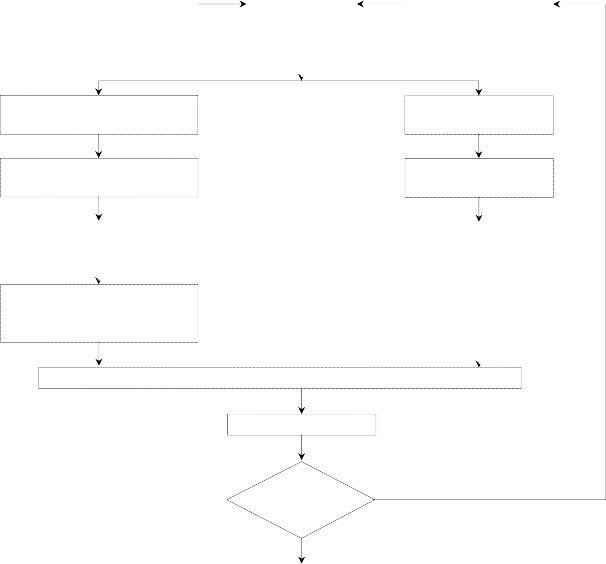
Drawings, Reports,
Acceptable Corrosion Allowance
Design Related Risk
Coating Condition Usage of Tanks
Corrosion Risk
Collection of Information | |
Analyse:
Hull Damage of This Ship
Coating Condition Usage of Tanks
Analyse Hull Damage for Similar Ships(Where Available)
Corrosion Damage of This Ship
Hull Damage: General Experience | |
Corrosion Damage for Similar Ships(Where Available) | |
Present Areas where Damage has been found and Risks considered high. Mark Sketches or Drawings
Nominate Location for Thickness Measurement and Close-up Survey
Survey Programme
Acceptance by Class & Owner
Survey
2. Prior to the development of the survey programme, the survey planning questionnaire is to be com-
pleted by the Owner based on the information set out in Annex 1-3, Table 2 of
and forwarded to the Society.
the Guidance,
98 Guidance Relating to the Rules for the Classification of Steel Ships 2015
Pt 1 Classification and Surveys
Annex 1-3 Example of the Survey Programme and the Survey Planning Questionnaire Pt 1, Annex 1-3
![]()
Table 1 Example of the Survey Programme

SURVEY PROGRAMME 
For Special Survey No. / Intermediate Survey at years of age,
scheduled from to at .
(If the commencement-completion survey system is applied, outlines of each survey are to be listed in the next page)
Basic information and particulars
Name of ship : | |
Class No. : | IMO No. : |
Class Notation : | |
Flag State : | |
Port of registry : | |
Gross tonnage : | |
Deadweight(metric tones) : | |
Length between perpendiculars(m) : | |
Shipbuilder : | |
Hull number : | |
Date of delivery of the ship : | |
Date of build / major conversion : | / |
Owner : | |
Thickness measurement company : | |


Prepared by the Owner in co-operation with the Society;
Owner's representative : | Classification Society : | ||||
( | Signature Name Place / Date | ) | ( | Signature Name Place / Date | ) |
Guidance Relating to the Rules for the Classification of Steel Ships 2015 99
Pt 1 Classification and Surveys
Annex 1-3 Example of the Survey Programme and the Survey Planning Questionnaire Pt 1, Annex 1-3
![]()
SURVEY PROGRAMME
Outlines of each commencement-completion survey
Docking | Overall | Close-up | Thickness | Tank | Suspect |
(Yes/No) | Survey | Survey | measurement | Testing | Area |
![]()
Date Place
![]()


![]()
1. Preamble
1.1 Scope
1.1.1 The present survey programme covers the minimum extent of Overall Surveys, Close-up Surveys, thickness measurements and pressure testing within the cargo (length) area, cargo holds/tanks, ballast tanks, including fore and aft peak tanks, required by the Rules.
1.1.2 The arrangements and safety aspects of the survey are to be acceptable to the attending Surveyor(s).
1.2 Documentation
All documents used in the development of the survey programme are survey as required by the relevant requirements specified in the Rules.
to be available onboard during the
100 Guidance Relating to the Rules for the Classification of Steel Ships 2015
Pt 1 Classification and Surveys
Annex 1-3 Example of the Survey Programme and the Survey Planning Questionnaire Pt 1, Annex 1-3
![]()
SURVEY PROGRAMME
2. Arrangement of cargo holds, tanks and spaces
This section of the survey programme is to provide information(either in the form of plans or text) on the arrangement of cargo holds, tanks and spaces that fall within the scope of the survey.
Guidance Relating to the Rules for the Classification of Steel Ships 2015 101
Pt 1 Classification and Surveys
Annex 1-3 Example of the Survey Programme and the Survey Planning Questionnaire Pt 1, Annex 1-3
![]()
SURVEY PROGRAMME
3. List of cargo holds, tanks and spaces with information on their use, extent of coatings and corrosion prevention system
This section of the survey programme is to indicate any changes relating to (and is to update) the information on the use of the holds and tanks of the ship, the extent of coatings and the corrosion prevention system provided in the survey planning questionnaire.
102 Guidance Relating to the Rules for the Classification of Steel Ships 2015
Pt 1 Classification and Surveys
Annex 1-3 Example of the Survey Programme and the Survey Planning Questionnaire Pt 1, Annex 1-3
![]()
SURVEY PROGRAMME
4. Conditions for survey
This section of the survey programme is to provide information on the conditions for survey, e.g. information regarding cargo hold and tank cleaning, gas freeing, ventilation, lighting, etc.
![]()
Hold/Tank/Space Cleaning Gas freeing Ventilation Lighting Etc.
![]()


![]()
Guidance Relating to the Rules for the Classification of Steel Ships 2015 103
Pt 1 Classification and Surveys
Annex 1-3 Example of the Survey Programme and the Survey Planning Questionnaire Pt 1, Annex 1-3
![]()
SURVEY PROGRAMME
5. Provisions and method of access to structures
This section of the survey programme is to indicate any changes relating to (and is to update) the information on the provisions and methods of access to structures provided in the survey planning questionnaire.
104 Guidance Relating to the Rules for the Classification of Steel Ships 2015
Pt 1 Classification and Surveys
Annex 1-3 Example of the Survey Programme and the Survey Planning Questionnaire Pt 1, Annex 1-3
![]()
SURVEY PROGRAMME
6. List of equipment for survey
This section of the survey programme is to identify and list the equipment that will be made available for carrying out the survey and the required thickness measurements.
(e.g. thickness measurement equipment, fracture detection equipment, explosimeter, oxygen-meter, breathing apparatus, lifelines, riding belts with rope and hook, whistles, safe lighting, protective clothing(safety helmet, gloves, safety shoes, etc.), etc.)
![]()
Equipment Sets Description Used for
![]()


![]()
Guidance Relating to the Rules for the Classification of Steel Ships 2015 105
Pt 1 Classification and Surveys
Annex 1-3 Example of the Survey Programme and the Survey Planning Questionnaire Pt 1, Annex 1-3
![]()
SURVEY PROGRAMME
7. Survey requirements
7.1 Overall Survey
This section of the survey programme is to identify and list the spaces that are to undergo an Overall Survey for the ship in accordance with the Rules.
![]()
Hold/Tank/Space Remarks
![]()


![]()
106 Guidance Relating to the Rules for the Classification of Steel Ships 2015
Pt 1 Classification and Surveys
Annex 1-3 Example of the Survey Programme and the Survey Planning Questionnaire Pt 1, Annex 1-3
![]()
SURVEY PROGRAMME
7.2 Close-up Survey
This section of the survey programme is to identify and list the hull structures that are to undergo a Close-up Survey for the ship in accordance with the Rules.
![]()
Hold/Tank/Space Areas for Close-up Survey
![]()


![]()
Guidance Relating to the Rules for the Classification of Steel Ships 2015 107
Pt 1 Classification and Surveys
Annex 1-3 Example of the Survey Programme and the Survey Planning Questionnaire Pt 1, Annex 1-3
![]()
SURVEY PROGRAMME
8. Identification of tanks for tank testing and pipes for pipe testing
This section of the survey programme is to identify and list the cargo holds and tanks that are to undergo tank testing for the ship and the pipes that are to undergo pipe testing(for chemical tankers) in accordance with the Rules.
![]()
Hold/Tank/Pipe Remarks
![]()


![]()
108 Guidance Relating to the Rules for the Classification of Steel Ships 2015
Pt 1 Classification and Surveys
Annex 1-3 Example of the Survey Programme and the Survey Planning Questionnaire Pt 1, Annex 1-3
![]()
SURVEY PROGRAMME
9. Identification of areas and sections for thickness measurements This section of the survey programme is to identify and list the areas and sections where thickness measurements are to be taken in accordance with the Rules.
![]()
Hold/Tank Areas and sections for thickness measurement
![]()


![]()
Guidance Relating to the Rules for the Classification of Steel Ships 2015 109
Pt 1 Classification and Surveys
Annex 1-3 Example of the Survey Programme and the Survey Planning Questionnaire Pt 1, Annex 1-3
![]()
SURVEY PROGRAMME
10. Minimum thickness of hull structures
This section of the survey programme is to specify the minimum thickness for hull structures of the ship that are subject to survey. (indicate either (a) or preferably (b), if such information is available):
(a) ![]() Determined from the attached wastage allowance table and the original thickness to the hull structure plans of the ship;
Determined from the attached wastage allowance table and the original thickness to the hull structure plans of the ship;
(b)
![]()
Given in the following table(s):
![]()
Area or location
Original as-built thickness(mm)
Minimum thickness(mm)
Substantial corrosion thickness(mm)
![]()


![]()
Note: The wastage allowance tables are to be attached to the survey programme.
For vessels built under IACS Common Structural Rules(Pt 11, Pt 12 or Pt 13), the renewal thickness of the hull structure elements is indicated in the appropriate drawings.
110 Guidance Relating to the Rules for the Classification of Steel Ships 2015
Pt 1 Classification and Surveys
Annex 1-3 Example of the Survey Programme and the Survey Planning Questionnaire Pt 1, Annex 1-3
![]()
SURVEY PROGRAMME
11. Thickness measurement company
This section of the survey programme is to identify changes, if any, relating to the information on the thickness measurement company provided in the survey planning questionnaire.
Guidance Relating to the Rules for the Classification of Steel Ships 2015 111
Pt 1 Classification and Surveys
Annex 1-3 Example of the Survey Programme and the Survey Planning Questionnaire Pt 1, Annex 1-3
![]()
SURVEY PROGRAMME
12. Damage experience related to the ship
This section of the survey programme is to, using the tables provided below, provide details of the hull damages for at least the last three years in way of the cargo holds/tanks, ballast tanks and void spaces within the cargo (length) area. These damages are subject to survey.
Hull damages sorted by location for the ship
![]()
Cargo hold, tank or space number or area
Possible cause,
if known
Description of the damages
Location Repair
Date of repair
![]()


![]()
Hull damages for sister or similar ships (if available) in the case of design related damage
![]()
Cargo hold, tank or space number or area
Possible cause,
if known
Description of the damages
Location Repair
Date of repair
![]()


![]()
112 Guidance Relating to the Rules for the Classification of Steel Ships 2015
Pt 1 Classification and Surveys
Annex 1-3 Example of the Survey Programme and the Survey Planning Questionnaire Pt 1, Annex 1-3
![]()
SURVEY PROGRAMME
13. Areas identified with substantial corrosion from previous surveys
This section of the survey programme is to identify and list the areas of substantial corrosion from previous surveys.
![]()
Hold/Tank/Space Areas of substantial corrosion Date and kind of survey
![]()


![]()
Guidance Relating to the Rules for the Classification of Steel Ships 2015 113
Pt 1 Classification and Surveys
Annex 1-3 Example of the Survey Programme and the Survey Planning Questionnaire Pt 1, Annex 1-3
![]()
SURVEY PROGRAMME
14. Critical structural areas and suspect areas
This section of the survey programme is to identify and list the critical structural areas and the suspect areas, when such information is available.
![]()
Hold/Tank/Space Critical structural areas Suspect areas
![]()


![]()
114 Guidance Relating to the Rules for the Classification of Steel Ships 2015
Pt 1 Classification and Surveys
Annex 1-3 Example of the Survey Programme and the Survey Planning Questionnaire Pt 1, Annex 1-3
![]()
SURVEY PROGRAMME
15. Other relevant comments and information
This section of the survey programme is to provide any other comments and information relevant to the survey.
Guidance Relating to the Rules for the Classification of Steel Ships 2015 115
Pt 1 Classification and Surveys
Annex 1-3 Example of the Survey Programme and the Survey Planning Questionnaire Pt 1, Annex 1-3
![]()
SURVEY PROGRAMME
16. Appendices
Appendix 1 - List of plans
The Rules require that main structural plans of cargo holds/tanks and ballast tanks (scantling drawings), including information regarding use of high tensile steel (HTS), clad steel and stainless steel(for chemical tankers) are to be available. This appendix of the survey programme is to identify and list the main structural plans which form part of the survey programme.
Appendix 2 - Survey planning questionnaire
The survey planning questionnaire, which has been submitted by the Owner, is to be appended to the survey programme.
Appendix 3 - Other documentation
This part of the survey programme is to identify and list any other documentation that forms part of the plan.
116 Guidance Relating to the Rules for the Classification of Steel Ships 2015
Pt 1 Classification and Surveys
Annex 1-3 Example of the Survey Programme and the Survey Planning Questionnaire Pt 1, Annex 1-3
![]()
Table 2 Example of the Survey Planning Questionnaire